I recently developed a Matrix Orbital compatible serial "backpack" for a spare 16x2 LCD I had. It's serial-port powered (parasitic powering from DTR/RTS, no backlight), using a PIC16F628 (18 pin with UART) and coded in HiTech PICC (very good but very expensive - I'm using it from work, but there's a free lite version that supports F877 and F627). Baudrate is fixed at 9600, but it can probably do 19200 if I implemented proper buffering.
If I'd known about X7JAY7X's version I wouldn't have bothered, but it's been interesting work. I haven't done a lot of PIC work so far, and this is my first real project in PICC. It's based on an LCD terminal for a linux carPC mp3 player, written ages ago by Bob Blick - see http://www.bobblick.com/techref/project ... dterm.html
I've implemented a similar command subset to X7JAY7X apart from the backlight functions. No GPOs or other fancy stuff, so it sounds like X7JAY7X is well ahead of me by now... so I'll be trying his implementation when I get a chance.
If anyone's interested, I can provide source/hex/schematic...
Matt.
EDIT: The download links in the rest of this thread are broken, so I've attached the source code, hex for PIC16F628 and schematic to this post as a ZIP. Log in to see the attachment.
Our new official repo is on github
LCD Smartie version 5.6 is released!
Download it now: https://github.com/LCD-Smartie/LCDSmartie/releases
LCD Smartie version 5.6 is released!
Download it now: https://github.com/LCD-Smartie/LCDSmartie/releases
PIC Serial Backpack II
Moderators: _X7JAY7X_, caesar, IFR, mattcro, limbo, Fast351, hydrolisk1792
-
mattcro
- Forum Supporter
- Posts: 590
- Joined: March 8th, 2006, 1:58 pm
- Location: Scotland
PIC Serial Backpack II
You do not have the required permissions to view the files attached to this post.
-
_X7JAY7X_
- Hardware Genie - Plugin Author
- Posts: 374
- Joined: February 16th, 2005, 10:24 pm
- Location: Michigan
Matt, I have been working on and off on the 877 with bootloader support. It works fine. I just need to test all of the GPO and Buttons before I post it.
I am also working on 4x40 support for the 628 or 877. It seems to work fine but it has a few bugs.
I am hoping to eventually sell the bootloaded 16F877 or a preprogrammed 16F628 for a very reasonable price. People do not want to buy a programmer just to use it a few times. I have had some interested in selling some of these projects as well.
If you would like to be a tester on any of these projects let me know.
J
-
mattcro
- Forum Supporter
- Posts: 590
- Joined: March 8th, 2006, 1:58 pm
- Location: Scotland
Hi J,
I've got your 16F628 v2.1 firmware working nicely on my protoboard here in place of my code - only minor wiring changes, as it turns out. I was using an external ceramic resonator and R-C reset components, but it looks like they are overkill.
Your implementation seems to be a bit more robust than mine as far as I can tell from some quick tests. Mine sometimes locked up at switch-on if there was data being sent. Did you use software buffering on the RS232 receive? I didn't use any interrupts or buffering - it seemed to be able to cope with 9600baud, but I suspect that Smartie inserts delays for the commands that take extra time (clear screen, etc).
I'm thinking about getting a 20x2 or maybe 20x4 backlit module (only got a 16x2 currently) and making a proper drive bay housing using a scrap HDD drive-bay carrier/panel with a few buttons and outputs, so I'd be interested in trying/testing any firmware revisions you make. If you plan to publish the source, I'll be taking a look at it.
I have a spare PIC16F877 (not 877A) and PIC16F628 at home, with Tait programmer and ICProg, plus loads of other components to experiments with buttons, GPOs etc. But I'll be moving home in the next month or so, so might not get much chance to try anything yet...
Matt.
-
_X7JAY7X_
- Hardware Genie - Plugin Author
- Posts: 374
- Joined: February 16th, 2005, 10:24 pm
- Location: Michigan
I used the UART for the receive. My compiler does all the work for me as far as setup and using it. I think that v2.1 could handle 19,200 but I havent tried it. I may need to use 8 bit LCD interface for anything higher than 9,600.
Let me know if you have any suggestions and when you are ready for some testing.
J
Let me know if you have any suggestions and when you are ready for some testing.
J
-
mattcro
- Forum Supporter
- Posts: 590
- Joined: March 8th, 2006, 1:58 pm
- Location: Scotland
I've been fiddling with my MO-compatible serial backpack again, and now have variable backlight level (PWM) and support for up to 4x20 LCD modules (experimental).
I've ditched the 4MHz external oscillator in favour of the internal RC osc as this is perfectly adequate. Non-backlit LCDs can be powered from the serial port, but backlit modules require a separate (wall-wart, plug-pack etc) 9V or so supply. Hardware is basically compatible with X7JAY7X's implementation of the same kind of backpack at http://www.freewebs.com/x7jay7x/ and mentioned on this forum.
I've also added an internal character translation table that converts accented characters (European grave, acute, umlaut, cedilla etc.) to the nearest equivalent that the LCD can produce. There appear to be two main versions of the HD44780 type controller: one with European extended character set, and a (probably more common) Japanese version. I have the Japanese version.
Source code (HiTech PICC), hex for PIC16F628 and schematic available for anyone who's interested here.
Matt.
Last edited by mattcro on June 16th, 2006, 9:49 pm, edited 1 time in total.
-
jwildesbr
- Posts: 2
- Joined: May 9th, 2006, 8:05 pm
Serial BackPack from Matt
Hi Matt,
Your link is broken.
Can you send the files of serial backpack to me ?
My email is jwildes@hotmail.com.
I have a PIC 16F628 and a 16X2 LCD and i?d like to build a serial lcd to use in my computer or other pic projects.
Best regards,
Your link is broken.
Can you send the files of serial backpack to me ?
My email is jwildes@hotmail.com.
I have a PIC 16F628 and a 16X2 LCD and i?d like to build a serial lcd to use in my computer or other pic projects.
Best regards,
-
mattcro
- Forum Supporter
- Posts: 590
- Joined: March 8th, 2006, 1:58 pm
- Location: Scotland
Hey all,
I finally got around to making up a proper enclosure for my external serial LCD after some time away from electronics...
I just used a scrap plastic enclosure and made up an alu front panel onto which I mounted the LCD, 5 buttons and 1 GPO LED.
Power is supplied from the PC 12V rail via an outlet socket on a backplane blanking plate. I made up a serial/power combo cable with a DIN-4 connector (chosen to be unique so it can't be mistakenly plugged into anything else) that plugs into the rear of the LCD enclosure.
I arranged the 5 buttons as a navigation/menu type control, although I'm mainly using them to switch screens and control media playback. There's a single warning/notification LED (GPO1) that I haven't decided what to use for yet. I also fitted a "power on" LED - with a bit of multiplexing, this could be used as a second GPO LED.

The open enclosure showing the controller board with PIC16F628, MAX232 and a handful of resistors, capacitors etc.
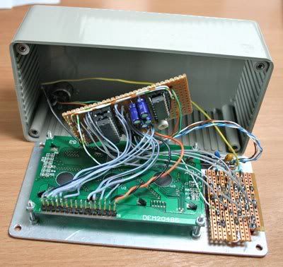
The rear of the front panel. The LCD module is bolted to the front panel, and one of the bolts (rear right) also holds the 7805 regulator (front panel is the heatsink). The small board to the right holds the buttons and LEDs. The power/serial connector is just visible in the botton left of the enclosure.


The 4-pin DIN connector provides power and serial I/O. I fitted 1.5m of cable (junk Cat-3 UTP) so the LCD can be placed anywhere on the desk. The DC power connector plugs into a socket outlet on a backplane blanking plate, which provides 12V from a disk drive connector via a 1A poly fuse.

My system info screen. Top line shows CPU usage, temp and fan speed [with custom char fan symbol $CustomChar(1,0,25,11,4,26,19,0,0)$Chr(176) ]. line 2 shows mem and page file usage. Line 3 shows free mem. Line 4 shows current time, and GPU temp.

My Winamp screen. Line 1 is artist, line 2 is track title (these scroll if necessary using scrollpad.dll), line 3 is custom char state symbol (play/pause/stop), current/total track time and bitrate. Line 4 is CPU and mem info.
Project schematic and PIC code/hex here:
http://uk.geocities.com/matt.crowley@bt ... ectronics/
Matt.
I finally got around to making up a proper enclosure for my external serial LCD after some time away from electronics...
I just used a scrap plastic enclosure and made up an alu front panel onto which I mounted the LCD, 5 buttons and 1 GPO LED.
Power is supplied from the PC 12V rail via an outlet socket on a backplane blanking plate. I made up a serial/power combo cable with a DIN-4 connector (chosen to be unique so it can't be mistakenly plugged into anything else) that plugs into the rear of the LCD enclosure.
I arranged the 5 buttons as a navigation/menu type control, although I'm mainly using them to switch screens and control media playback. There's a single warning/notification LED (GPO1) that I haven't decided what to use for yet. I also fitted a "power on" LED - with a bit of multiplexing, this could be used as a second GPO LED.
The open enclosure showing the controller board with PIC16F628, MAX232 and a handful of resistors, capacitors etc.
The rear of the front panel. The LCD module is bolted to the front panel, and one of the bolts (rear right) also holds the 7805 regulator (front panel is the heatsink). The small board to the right holds the buttons and LEDs. The power/serial connector is just visible in the botton left of the enclosure.
The 4-pin DIN connector provides power and serial I/O. I fitted 1.5m of cable (junk Cat-3 UTP) so the LCD can be placed anywhere on the desk. The DC power connector plugs into a socket outlet on a backplane blanking plate, which provides 12V from a disk drive connector via a 1A poly fuse.
My system info screen. Top line shows CPU usage, temp and fan speed [with custom char fan symbol $CustomChar(1,0,25,11,4,26,19,0,0)$Chr(176) ]. line 2 shows mem and page file usage. Line 3 shows free mem. Line 4 shows current time, and GPU temp.
My Winamp screen. Line 1 is artist, line 2 is track title (these scroll if necessary using scrollpad.dll), line 3 is custom char state symbol (play/pause/stop), current/total track time and bitrate. Line 4 is CPU and mem info.
Project schematic and PIC code/hex here:
http://uk.geocities.com/matt.crowley@bt ... ectronics/
Matt.
-
mattcro
- Forum Supporter
- Posts: 590
- Joined: March 8th, 2006, 1:58 pm
- Location: Scotland
Hey thanks, megabyte. It's nothing special really!
If you plan to use the same style of enclosure, just use the original plastic lid, unless you really want aluminium for the front panel. I got the box for nothing because the original lid was missing
If I could be bothered doing it properly, I'd get the button legends milled into the alu or get some proper lettering printed on...
My enclosure is approx 150mm wide, 80mm high and 45mm deep (looking at the front panel) excluding the lid. The LCD and button PCB can just squeeze in with a tiny bit of space to spare.
-
pasan
- Posts: 54
- Joined: March 13th, 2007, 11:52 am
- Location: Sri Lanka
Hey bro. How to re edit that start up message in ur ASM sutable for my 16X2 lcd ( if i can put my name on it, it wil be grate )mattcro wrote:I think it will still work with a 2x16 LCD. The internal startup message will not be displayed properly because it's designed for a 4x20 LCD, but that doesn't affect the operation in Smartie.
Thanks
-
pasan
- Posts: 54
- Joined: March 13th, 2007, 11:52 am
- Location: Sri Lanka
Hey Mr. X7JAY7X,_X7JAY7X_ wrote:Pasan, most people that make free firmware put their name on it. It is a way of getting credit for their work and to prevent people from stealing/selling it.
J
Im a student. Im learning about pic nowadays. I dont know that much pic codings. When it come to LCDs. Its much harder to me at this moment. Ya ur 100% correct lots of people try to copy something and commercialize it.
Thanxs for the project and reply
-
mattcro
- Forum Supporter
- Posts: 590
- Joined: March 8th, 2006, 1:58 pm
- Location: Scotland
J is right - I'd like to keep my name on it somewhere 
I did consider having an option to change the startup screen on my LCD to a user defined text, but I don't know how many people (if any!) are using my design. It also depends on the display dimensions (rows and columns) on the LCD you use. It's not worth it just for myself. I can't remember if there's a Matrix Orbital command to do that...
Anyway, I did the programming using the HiTech C compiler so there isn't any assembler code unfortunately. You'd have to use the C source code, but it's for a specific compiler that not many folks have except in a commercial environment (I have access to it at work).
For hobbyists wanting to do C programming on PICs, using PIC18 micros with the (free) student edition of Microchip's C18 compiler is an option - I'm experimenting with it at home. The PIC18 series chips are generally more expensive than PIC16 but the software is free. It's not really aimed at casual hobbyists though - more a commercial environment from what I've seen so far.
-
pasan
- Posts: 54
- Joined: March 13th, 2007, 11:52 am
- Location: Sri Lanka
Thanksmattcro wrote:J is right - I'd like to keep my name on it somewhere
I did consider having an option to change the startup screen on my LCD to a user defined text, but I don't know how many people (if any!) are using my design. It also depends on the display dimensions (rows and columns) on the LCD you use. It's not worth it just for myself. I can't remember if there's a Matrix Orbital command to do that...
Anyway, I did the programming using the HiTech C compiler so there isn't any assembler code unfortunately. You'd have to use the C source code, but it's for a specific compiler that not many folks have except in a commercial environment (I have access to it at work).
For hobbyists wanting to do C programming on PICs, using PIC18 micros with the (free) student edition of Microchip's C18 compiler is an option - I'm experimenting with it at home. The PIC18 series chips are generally more expensive than PIC16 but the software is free. It's not really aimed at casual hobbyists though - more a commercial environment from what I've seen so far.
-
mattcro
- Forum Supporter
- Posts: 590
- Joined: March 8th, 2006, 1:58 pm
- Location: Scotland
For my PIC backpack, you need to use matrix.dll with the serial port speed set to 19200. For example, my Smartie installation has COM1,19200 in the startup parameters box. If you try with 9600 baud, you will get all sorts of junk on the display (I just did it myself to check ). It looks like Smartie's default setting for Matrix Orbital is 9600 baud, which is the normal rate for MO displays, but I decided to use the faster (also MO standard) rate.
If you have already got that set ok, I'm not sure what the problem is. Which PIC processor are you using? I think I compiled v0.87 for PIC16F628 (not 628A, which has slightly different programming I think)
If you have already got that set ok, I'm not sure what the problem is. Which PIC processor are you using? I think I compiled v0.87 for PIC16F628 (not 628A, which has slightly different programming I think)
-
pasan
- Posts: 54
- Joined: March 13th, 2007, 11:52 am
- Location: Sri Lanka
Thanks for the reply.mattcro wrote:For my PIC backpack, you need to use matrix.dll with the serial port speed set to 19200. For example, my Smartie installation has COM1,19200 in the startup parameters box. If you try with 9600 baud, you will get all sorts of junk on the display (I just did it myself to check
If you have already got that set ok, I'm not sure what the problem is. Which PIC processor are you using? I think I compiled v0.87 for PIC16F628 (not 628A, which has slightly different programming I think)

-
mattcro
- Forum Supporter
- Posts: 590
- Joined: March 8th, 2006, 1:58 pm
- Location: Scotland
Either circuit should work fine - one difference is the +V capacitor (at the top of your schematic) connection, and either way is OK (-ve end of capacitor to GND or Vcc). The only other difference is that I added handshaking loopback lines on the serial port, because no handshaking is used by the PIC. These are optional. My display is built exactly according to my schematic and works fine on 2 different PCs.
What shows on the display when Smartie starts (or when you set the matrix.dll options)? Any recognizable text, or rapidly scrolling random junk?
What shows on the display when Smartie starts (or when you set the matrix.dll options)? Any recognizable text, or rapidly scrolling random junk?
-
pasan
- Posts: 54
- Joined: March 13th, 2007, 11:52 am
- Location: Sri Lanka
When I set that matrix.dll its shows me some text with lots of random junk.mattcro wrote:Either circuit should work fine - one difference is the +V capacitor (at the top of your schematic) connection, and either way is OK (-ve end of capacitor to GND or Vcc). The only other difference is that I added handshaking loopback lines on the serial port, because no handshaking is used by the PIC. These are optional. My display is built exactly according to my schematic and works fine on 2 different PCs.
What shows on the display when Smartie starts (or when you set the matrix.dll options)? Any recognizable text, or rapidly scrolling random junk?
Hey in ur cct u didn't give that power line.

I think max need that 16 pin power line.
I'll try it again.
Thanks for the reply.
-
mattcro
- Forum Supporter
- Posts: 590
- Joined: March 8th, 2006, 1:58 pm
- Location: Scotland
The MAX232 definitely needs the power supply connections!
On my schematic, the power connections for the MAX232 are shown separately to the chip, which can be confusing especially since the other devices have their power supply pins on the device symbol . That's just how the schematic library I used works.
The MAX232 power connections (pins 15 and 16) are shown at the top with the regulator - they are labelled IC3P (which means IC3 power).
On my schematic, the power connections for the MAX232 are shown separately to the chip, which can be confusing especially since the other devices have their power supply pins on the device symbol
The MAX232 power connections (pins 15 and 16) are shown at the top with the regulator - they are labelled IC3P (which means IC3 power).
-
pasan
- Posts: 54
- Joined: March 13th, 2007, 11:52 am
- Location: Sri Lanka
Oh.mattcro wrote:The MAX232 definitely needs the power supply connections!
On my schematic, the power connections for the MAX232 are shown separately to the chip, which can be confusing especially since the other devices have their power supply pins on the device symbol
The MAX232 power connections (pins 15 and 16) are shown at the top with the regulator - they are labelled IC3P (which means IC3 power).
Sorry